Two Short-Circuit Ratings a Datasheet Must Show
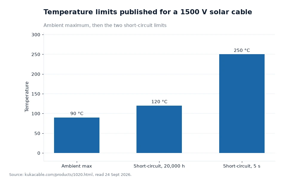
A PV cable datasheet should carry two short-circuit temperatures, because a fault can last five seconds while an overload can last for weeks. The 1500 V solar cable published by KUKA CABLE gives both figures: +120 °C that may be held for 20,000 hours, and +250 °C allowed for 5 seconds, both above an ambient ceiling of +90 °C.
Key takeaways
- The published short-circuit pair is +120 °C for 20,000 hours and +250 °C for 5 seconds, with +90 °C as the ambient maximum and −40 °C as the ambient minimum.
- By my own arithmetic those two durations sit 14.4 million times apart, since 20,000 hours is 72 million seconds.
- Ratings are DC 1.8/1.8 kV, checked on the finished cable at 6.5 kV AC, 50 Hz for five minutes, with a 10 kV spark test in the production line.
- The site publishes no current-carrying capacity table, so ampacity for a given installation has to come from the manufacturer rather than from the data sheet.
Why a cable needs two short-circuit figures
A fault cleared by a fuse or a breaker is over quickly, but the conductor still sees a burst of heat while the device decides to open. A partial fault that no device clears, or a string that is overloaded for a season, heats the cable far less intensely and far longer. A solar cable on the DC side of a PV system is expected to cope with both, and one number cannot describe the two events, which is why a serious data sheet prints a short window and a long window.
The material decides how the insulation answers. This cable family uses XLPO for the insulation and for the sheath, cross-linked by electron beam and described as low smoke halogen free. A cross-linked compound keeps its shape when it is hot, so it can absorb both a brief spike and a long soak without flowing away from the conductor.
The standards named for the range are TUV 2PfG 1169/08.2007, EN 50618:2014 and IEC 62930. TUV certification is treated on the client's own pages as the entry requirement for a PV cable rather than the finish, and the certificates page lists more than 30 certificate types covering TUV, IEC, CE, SAA and UL.
The three temperatures on the published page
The 1500 V cable page prints the ambient range as −40 °C to +90 °C and adds the two short-circuit values on the same line. The ambient figure describes the air around the cable; the short-circuit figures describe the conductor itself, which is allowed to run much hotter than its surroundings while a fault is present.
The same page lists DC 1.8/1.8 kV as the rated voltage, a test voltage of 6.5 kV AC at 50 Hz applied for five minutes to the finished cable, a 10 kV spark test during production, a minimum bending radius of 4 times the outer diameter, tensile strength before ageing of at least 8 N/mm² and elongation before ageing of at least 125%.
What the page does not carry is a current-carrying capacity table. No ampacity figures for any size appear on it, so a designer who needs to know how much current a 6 mm² conductor may carry in a given tray, at a given ambient temperature, has to ask the manufacturer instead of reading a number off the sheet.
What the long figure means in practice
Twenty thousand hours is a little over two years of continuous operation, by my own division of the published figure: 20,000 hours divided by 8,760 hours in a year is about 2.28 years. A cable that spends that long at +120 °C would be a cable in permanent fault, and the rating exists so that a designer knows the insulation is still expected to hold its properties through such an event.
Five seconds, by contrast, is a protection device doing its job. The gap between the two published figures, 72 million seconds against five, is what the pair of ratings is really describing: two completely different thermal events that a single limit could never cover.
The published figures are ceilings for insulation behaviour, not operating targets. Normal service is bounded by the +90 °C ambient value and by whatever conductor temperature the installation standard allows for the design.
The published limits in one table
Laid out in a row, the numbers read like a thermal envelope around the cable. Every value below comes from the manufacturer's 1500 V solar cable page; the middle column is the published figure and the right-hand column says which condition it applies to.
| Condition | Published value | What it describes |
|---|---|---|
| Ambient, cold end | −40 °C | Coldest surrounding air the cable is rated for |
| Ambient, hot end | +90 °C | Warmest continuous surrounding air |
| Short circuit, long window | +120 °C for 20,000 h | Conductor temperature during a sustained overload |
| Short circuit, short window | +250 °C for 5 s | Conductor temperature while protection clears a fault |
| Finished cable test | 6.5 kV AC, 50 Hz, 5 minutes | Dielectric strength of the completed cable |
| In-line test | 10 kV spark test | Insulation faults during production |
The last two rows are often left out of a summary, yet they are the ones a purchase order can point at. A buyer who quotes only the temperatures has no way to ask whether the cable was tested after assembly rather than in pieces.
Why the conductor size changes the answer
Copper carries heat away from the hot spot as well as current, so a heavier conductor is more comfortable near the short-circuit ceiling. The published table shows 4 mm² built from 56 strands of 0.29 mm, 6 mm² from 84 strands of the same wire and 10 mm² from 142 strands, with overall diameters of 5.5 mm, 6.0 mm and 7.5 mm.
Diameter also sets how tightly the cable may be bent, since the published rule is 4 times the outer diameter. By my own arithmetic on those figures, the 4 mm² cable takes a 22 mm radius, the 6 mm² cable 24 mm and the 10 mm² cable 30 mm, assuming one bend at room temperature with no tension applied.
A tight bend is not a thermal problem by itself, but a bend that strains the insulation leaves a thinner wall on the outside of the curve, and a thinner wall is what a fault current tests first.
Worked example: five seconds a year for twenty-five years
Suppose a string clears one fault per year, and each fault takes five seconds to clear. Over 25 years of service that is 25 times 5 seconds, which is 125 seconds of short-circuit heat by my own multiplication, against a published allowance of 20,000 hours at +120 °C.
Put the same 125 seconds next to the 20,000-hour figure and the long rating looks enormous, which is the point of publishing both. The five-second limit protects the cable against the event a designer cannot schedule; the 20,000-hour limit protects it against the event nobody intended, and both are stated for the conductor rather than for the air around the tray.
Frequently asked questions
Which short-circuit figure belongs on a purchase specification?
Ask for both. The manufacturer publishes +250 °C for 5 seconds and +120 °C for 20,000 hours for its 1500 V solar cable, with −40 °C to +90 °C as the ambient range. The two numbers describe different events, so a specification that carries only one of them leaves the other condition unstated and cannot be compared with a competing offer.
Does the +250 °C figure mean the cable can run that hot?
No. It describes what the insulation is expected to survive while a protective device clears a fault, not a working temperature. Normal operation sits inside the published ambient range of −40 °C to +90 °C. The manufacturer's site publishes no current-carrying capacity table, so ask for the ampacity figures that match the installation before treating either short-circuit value as spare margin.
What to put on the next enquiry
Name the two short-circuit figures you expect, the ambient range of the site, and the test that proves the finished cable rather than the materials. Then ask for the data sheet of the exact size you plan to buy and the test report that goes with it, so the printed values can be checked against the cable that arrives.
The manufacturer's own test list covers water resistance, ultraviolet weathering, abrasion, cold bending, cold elongation, tensile strength after ageing, solderability, static flexibility and construction plus dimensional checks, and its laboratory has been described as ISO/IEC 17025 since December 2015. Free samples and data sheets can be requested through the site; prices, minimum quantities and lead times are not published there.
Every temperature limit in this article comes from the manufacturer's own website; the ambient and short-circuit values were recorded 24 Sept 2026[1].